Remember how we have the diode blink when connecting with the Phone to the Raspberry Pi. Now we would like to make the car lights blink when connecting with the Phone to the Raspberry Pi.

To access the full video please subscribe to FLLCasts.com
- #685
- 23 Feb 2018
TL. DR.
Connect a resistor to one of the cables for the lights. Connect the resistor to + on Raspberry Pi. Connect the diode minus to GND.
Car lights are diodes
They are probably different from the ones you have in the set, but all the diodes work in the same way. Our goal is to connect the diodes (that are car lights) to the Raspberry Pi controller. When the Raspberry Pi starts the lights will blink. This will be an indication for us that the operating system was correctly loaded and that the phone could connect to the Raspberry Pi.
Do we need a resistor?
As was the case previously when lighting the diode, we could use a resistor. If we don't use a resistor the lights could still work, but it is possible to burn the diode. All the cars that we've used up until now don't need a resistor. But it is better to add one resistor, just in case.
Remember the marks on the cables?
The cables for the diodes should be marked FL+ and FL-. Marking was done in the section Marking internal components in the Car.
How to connect the car lights to the Raspberry Pi Controller?
The cables of the lights should already be extended from previous steps in the course. In our case, the white cable is "-" (minus) and the red cable is "+" (plus). The white is extended with purple and the red is extended with orange. We change the colors on purpose to get used to the fact that there are jumper cables with different colors in the set. The end of the extension cable that is going to be connected to the Raspberry Pi must be of type F.


The cables continue on the other side of the car

Remember. The cables are connected in the following way. The Purple is connected to a White one so this is the "-" (minus). The orange is connected to the red one and this is the "+" (plus).
You must connect the purple cable to pin GND and Orange cable to pin 12 - GPIO 18. We leave this to you. No picture here :). Try to do it yourself and when you do and turn on the Raspberry Pi it will turn on the lights.
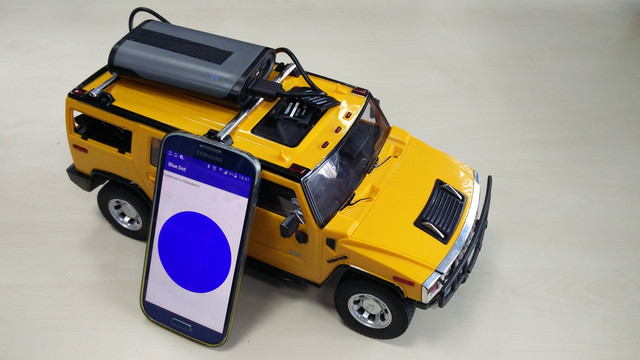
Ok ok. Here is a picture of the lights working :).

Courses and lessons with this Tutorial
This Tutorial is used in the following courses and lessons
Perfect STEM course. Module 1 - Smart Car with Raspberry PI
Disassemble a remote control car. Change the brain of the car with a smart computer like Raspberry Pi. Build a smart device with artificial intelligence that you could control from your phone and that could freely navigate itself in the real world and on the Internet. Use your hands. Develop programs for your robot and your phone. Be curious and invent.
The perfect course lives up to its name. You move through the content, we check it and return feedback to you.
In the end, you should be able to program and design smart devices that would make the world a better place. For everybody age 12+, 16+, 21+, 35+, etc. The hardware costs about 150$ and you could also use it in many of the other courses that we are planning to release.
- 118
- 42:47
- 136

Connecting Car Lights to Raspberry Pi controller
We would start connecting a lot of things to the Raspberry Pi. It will be good if we could have some way of referring to the pins on the Raspberry Pi. For example like Pin 5 or Pin 26. Luckily there is such a way.
- 3
- 0
- 5
- 3d_rotation 0