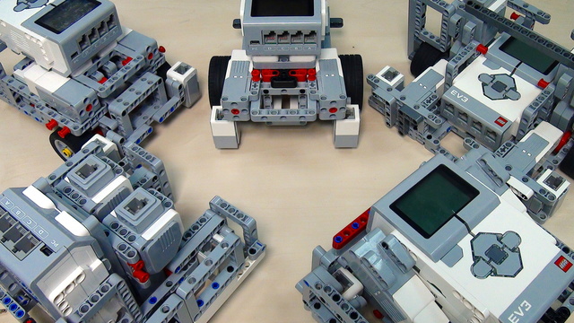
In Episode 58 we introduced you to a LEGO Mindstorms EV3 Modular robot. In this tutorial, we show you how we reached that construction. We start from a construction found on the Internet and take you through the process of examining and improving it, till we reach a more stable and reliable robot.
- #59
- 23 Nov 2014
- 10:29
You could find building instructions for the initial version of the robot under the materials tab and also take a look at Episode 58 for building instructions of the end version of the robot.
In this tutorial we take a look at several problems of the initial constructions found on the Internet:
-
the Back Wheel - it should be firmly attached to the robot. Best case is when the weight is uniformly distributed and falls on as much surface as possible.
-
the Axles of the Front Wheels - usually, when the axle of the front wheel is attached just to the motor it is loose and bend under the weight of the robot. This is why we built an outer frame to hold the axle.
-
the light or color sensors - it is always better if they have covers, which isolates from outer light, and are closely to the ground. For more on this take a look at Episode 3.
-
the whole robot is modular - that is not necessary, but always can be useful later, when you want to modify your construction.
In the next part we will improve the robot even further. Meanwhile we will be glad to hear from you, so do not forget to comment bellow.
Arrow designed by Juan Pablo Bravo from the Noun Project.
EV3 Competition Robot Light
Building instructions for a Light LEGO Mindstorms EV3 Competition Robot that could be used in LEGO Robotics competitions
English
In episode 58 we built an EV3 modular robot which actually is an updated version of this robot. In the next few minutes I'll point out some of the disadvantages of this construction and take you through the process of improving it till we reach the construction from tutorial 58.
I found this EV3 construction on the Internet and it's quite a good start for your robot. Still, there is room for improvement and we'll begin with the rear wheel. As you may notice, it's quite unstable. This is due to the fact it's attached with only these two pins here. This means the weight falls on them which makes the whole construction unreliable. I'll use the rear wheel I showed you in episode 58. The weight falls on these three beams here and it's equally distributed on the rear wheel which makes the whole construction more reliable. So, now I'll change the two rear wheels and then we'll continue with examining our robot. OK. I have attached the rear wheel and I have used this red pin with a stop bush to lock the rear wheel and now it's quite stable. I'll continue with examining the front wheels. As you see, they are quite loose and this might cause errors while the robot is making turns, which can cause problems if you want to orientate your robot on the field. A good technique to solve this problem is to build an outer frame which would hold the axles on which the tires are attached and in that way you will make the tires stable. The problem with this technique in our case is that if I build such an outer frame the robot will become too wide. This may cause problems when you want to maneuvre through the field. That is why, I will have to think of a way to narrow the construction. In our case, the best way to do so, is to flip this frame here at 90 degrees which will allow you to have your motors closer to one another. So, I will disassemble the construction and flip the frame and then we will see what we can do next. I have disassembled the construction and the first thing I have to do is to move this black pin one hole up because the frame does not have holes on this side - here and here. So, I'll attach the frame. Also, another small issue I'd like to cope with in the porcess of flipping the frame is the attachment of the two sensors. Currently, it's quite strange, as you can see. I personally do not really like it. So, I have built this thing here. The sensor will come into these two holes. Like this. So, I will do the same with the other motor and the other sensor and then we'll continue. I have attached the two motors and the two sensors. Now I can continue with assembling the medium motor. Till now, the medium motor was attached to the frame via these two pins only, which makes it unstable. As a whole, this is not a problem but after all we want to attach attachments to the third motor which will allow the whole construction to carry load. So, it's better if it is stable. That's why, I will use these T-shaped beams. This will allow me to have two pins - one here and one here - for attaching the motor to the frame. Now I will attach it. I have these four blue pins with which I'll attach the medium motor to the frame. It will go like this. I have the medium motor attached. Next I'll focus on these two beams. They will make it difficult to attach any gears to the medium motor. That is why, I will detach them. But when I do so, the front shield will fall down. Therefore, I'll take these pieces off and I'll use these angled beams. I'll attach them here and I'll build the front shield on them. Another plus of the angled beams is that I'll have holes here where I could attach some additional attachments. Now I'll build the front shield. OK. I have built the shield. I have also built these two things here to cover the light sensors. This will not allow any outer light to be detected by the light sensors which will make them more reliable and accurate. I'll use these angled beams here to attach the outer frame. And I'll use this one here to attach the shield to the base of the robot which will make it stronger. So, the shiled goes into these pins.
OK. Now I'll focus on the back frame. The back frame looks like this. But if I try to assemble it, it won't fit. That is why, I'll have to flip this frame at 90 degrees, like the front one. When I flip it, I'll continue with building the robot. I have reconstructed the back frame. I have flipped this frame at 90 degrees. and I have added these two beams of length 3. Now I can attach the back frame to the motors.
We have our base construction ready. Now I have to attach the brick. A simple problem that occurs is that after I have flipped the two frames it's higher here than there. So, I'll have to add a beam here. Like this. And then I'll attach the brick. I'll attach this beam to the frame and then attach the brick. Then we'll continue with the outer frame of the robot. OK. I have attached the beam to the frame and I've used long pins at the back, so that the pin will go further into the brick which will make the connection stronger. All I have to do now is attach the brick. First, I attach the back side and then I attach the four pins at the front. Now I have to build the outer frame. The outer frame should be connected here to the front shield and here to the back frame. Also, it should be connected to this axle, so that there is a point in building the outer frame. I'll assemble the outer frame and we'll see how it looks like. I have finally come to this construction for the outer frame and I have built a symmetrical one for the other side. I'll use these two black pins to attach the frame to the motor. This one will connect the frame to the front shield. At the back I will lock the frame with these two red pins. It should be assembled like this. Here it is. The key feature is that the axle of the tires goes into this hole here. Like this. Now the tire is more stable than the other one. When I lock the frame, you could see this. So, here and here. Now I'll repeat the same procedure on the other side and we'll finally take a look at our assembled robot. Finally, we have reached the construction from episode 58. In one of the future tutorials I will improve this construction even further like by using even fewer blue pins or I'll make it a little bit more stable. I'll be really glad to see any improvements made by you, so keep commenting below this video.
Courses and lessons with this Tutorial
This Tutorial is used in the following courses and lessons

FIRST LEGO League Competition. Constructing and Programming a Robot Base
This course if used by teams, mentors and students to structure the preparation for the Robotics Game of the FIRST LEGO League Robotics Competitions. One thing that is common each year at FLL is that experience matters a lot. Our goal with this course is to quickly bring new teams up to speed with experienced teams and to share some new tricks, patterns, constructions with the more experienced teams.
- 42
- 249:53
- 10

Constructing a robot base
Five different robot chassis. This is the goal of the series. To present ideas for different design of the robots and especially the robot bases. If the base is stable and balanced, then in could easily be extended. Let's start with the most simple of the five.
- 10
- 6
- 5
- 3d_rotation 9

Instructors Remote Training
If you are working with students and you want to introduce Robotics to your class or you want to mentor a FLL team, but you are insecure about your technical knowledge in the Robotics field, then this is the right place for you. Having in mind teachers' busy schedule, we have design two different schedules and added an option to design one just for you. FLLCasts's Mindstorms EV3 Robotics Online Training is the perfect match for any teacher.
After the completion of each task the participant has to upload his solution for verification.
- 136
- 280:11
- 156

Competition programming
In this episode, we introduce a LEGO Mindstorms EV3 version of competition robot construction. It is a modular construction, with medium motor for additional attachments and two light or colour sensors for orientating on the field.
- 7
- 0
- 8
- 3d_rotation 1

Instructors Remote Training
If you are working with students and you want to introduce Robotics to your class or you want to mentor a FLL team, but you are insecure about your technical knowledge in the Robotics field, then this is the right place for you. Having in mind teachers' busy schedule, we have design two different schedules and added an option to design one just for you. FLLCasts's Mindstorms EV3 Robotics Online Training is the perfect match for any teacher.
After the completion of each task the participant has to upload his solution for verification.
- 136
- 280:11
- 156

Mechanics
Gears could be a powerful tool for those who know how to use them appropriately. In this episode we introduce some of the basic terms and concepts behind using gears in your construction.
- 6
- 0
- 7
- 3d_rotation 0
