

Arduino Basic Course. Write your first Arduino program. Use example programs
For making the diode blink we just use one of the examples available in the Arduino Software.
- #312
- 15 Nov 2016
For making the diode blink we just use one of the examples available in the Arduino Software.

This is a remote control car. Have fun with it before disassembling it.

Developing a program for the Arduino is very easy. We need to do again three thigs:

You have the controller, you have the diode. The controller has a number of pins (holes). Where should you put the diode so that it starts blinking?
The small holes on the controller are called pins. On our controller we have 32 pins. The more pins that you have, the more elements you can controller with this microcontroller. For this video the interesting pins and 13 and GND

Time to experiment with the controller, the diode and the program that makes the diode blink. Don't be afraid to change the program. We've prepared a number of tasks for you in the course that you should definitely complete before moving forward.

For the current specific example we need two parts - the diode and the controller. In this episode we would show you which part is the controller, which are the jumpers and finally we would choose a diode.

As a result from the previous two videos we have a diode that is blinking. What will now happen with the diode if we remove the power and change the position of the legs.

Safety notice: There is current flowing in this device and you can touch the device with your bear hands. This is not dangerous, but there are a few things that you should consider especially in class.

In this episode we would modify the blinking diode program so that the diode will stay on for four seconds.

To correctly upload the blinking diode program to the controller we must first check some of the configurations of software. These are the "selected controller" and COM port

Every electronics tutorial, book or course about Raspberry Pi or Arduino will use a motor driver. Very few of the courses will actually explain why do you need a Motor Driver, what is it for?

We are about to connect the whole car with the lights and motors to the controller. Let's recap to know what is ahead of us, what would the process be and what is the end result of the next couple of sections when at the end we have a car controlled by the phone

We would start connecting a lot of things to the Raspberry Pi. It will be good if we could have some way of referring to the pins on the Raspberry Pi. For example like Pin 5 or Pin 26. Luckily there is such a way.

We need to extend the cables to be able to connect them to our Raspberry PI. We must also add new connectors at the end of the cables.

Give it a name and you will have power over it. I learned this from an MIT professor. So let's give the part of the car names. Then we could refer to them. Talk to them. Change them. Do all kinds of things with them. Give it a name and you will have power over it.

In the set for the Perfect Course, you have 3 different type of cables. They are called Breadboard Jumper Cables. We would need to use them to extend the default cables on the car and to connect the car components to our new controller

The power in the car comes from the batteries. The batteries are in a batteries holder. About 5 of them. Two cables are connected to the batteries holder. It is very important to identify which of those cables is the plus and which is the minus.
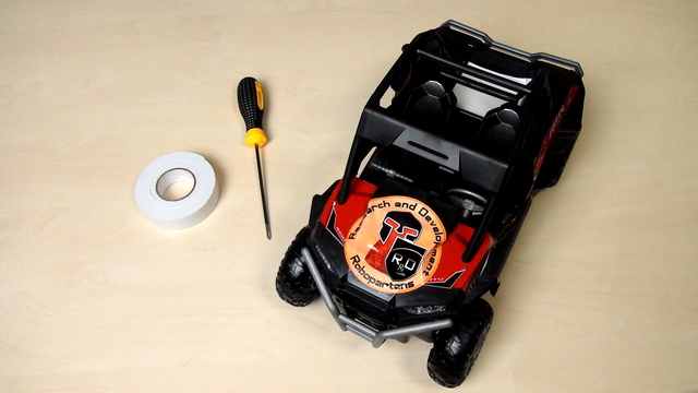
The course is designed to be used with almost every remote controlled car. The process of opening the car will be different for different cars but there are basic principles that you could follow.
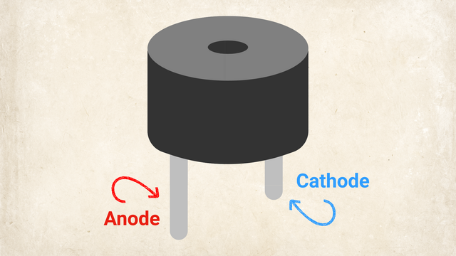
When you need a loud, straightforward alert for a project, like a timer, a security alarm, or a button-press confirmation, you don't always need complex music or variable tones. Active buzzers are simple "plug-and-play" components. Give them power, and they instantly make noise, saving you code and wiring hassle.
In this quick tutorial, you'll discover:
What an active electronic buzzer is and how it differs from a passive one.
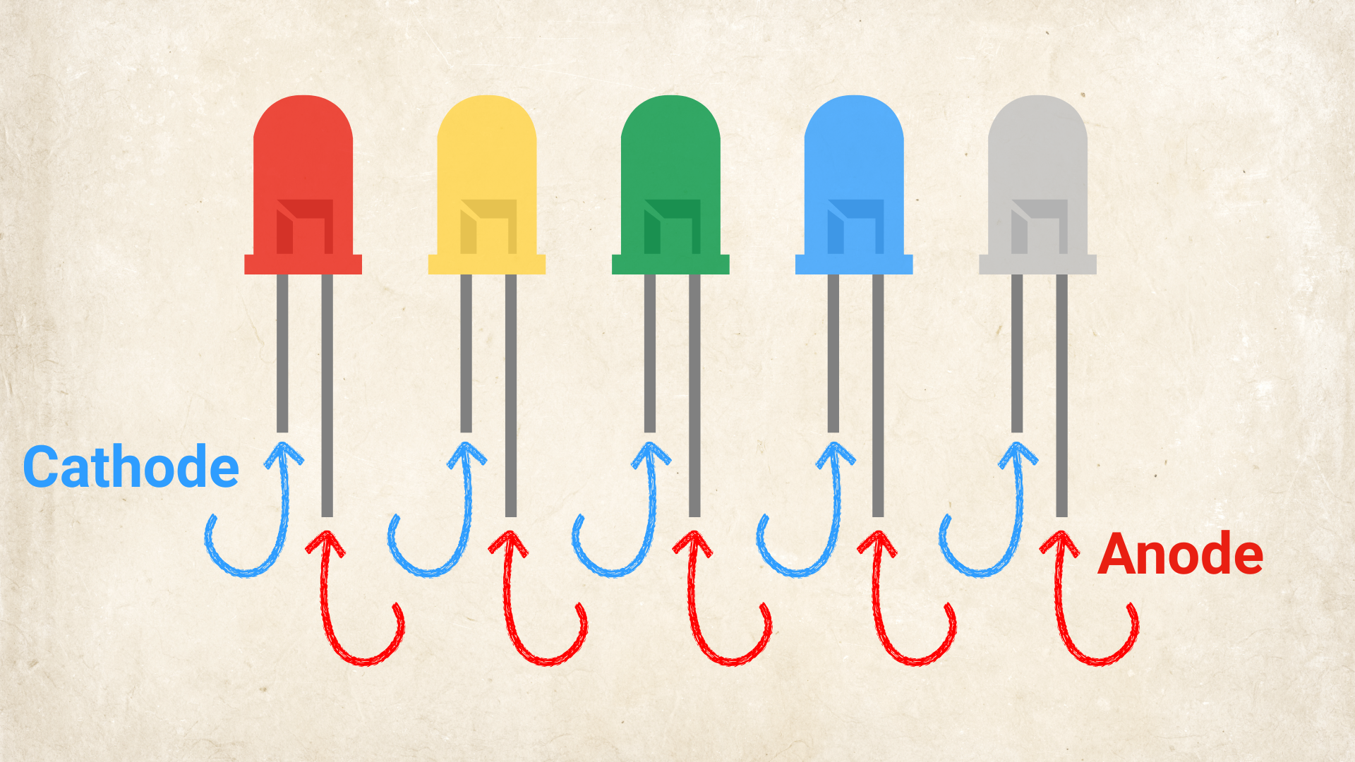
How to identify the anode (+) and cathode (-) pins.
How to wire and trigger an active buzzer using simple DC power or a microcontroller.
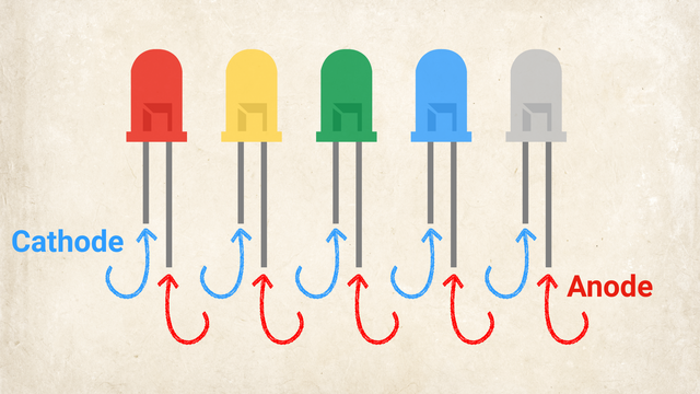
This tutorial covers the fundamentals of LEDs: how they function, how to identify their terminals, and how to safely power them without damaging the component.
Understanding LEDs is essential because they are the standard light source in modern electronics. Used in phones, monitors, custom PC builds, and basic microcontrollers like Arduino or ESP32.
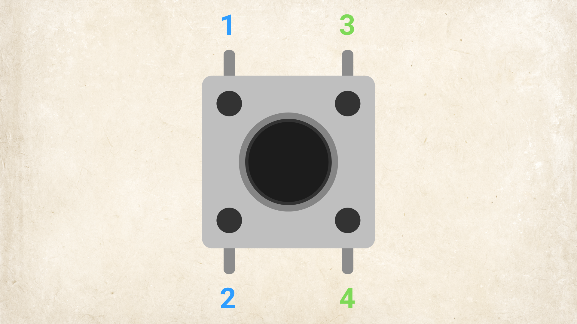
Push buttons allow users to interact with electronic circuits. Whether you are building an Arduino project, a game controller, or a custom gadget, you need these buttons to trigger actions, start programs, or change settings.
What you will learn:
What a tactile push button is.
How the 4 pins connect internally.
How to place the button correctly on a breadboard.
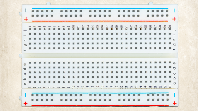
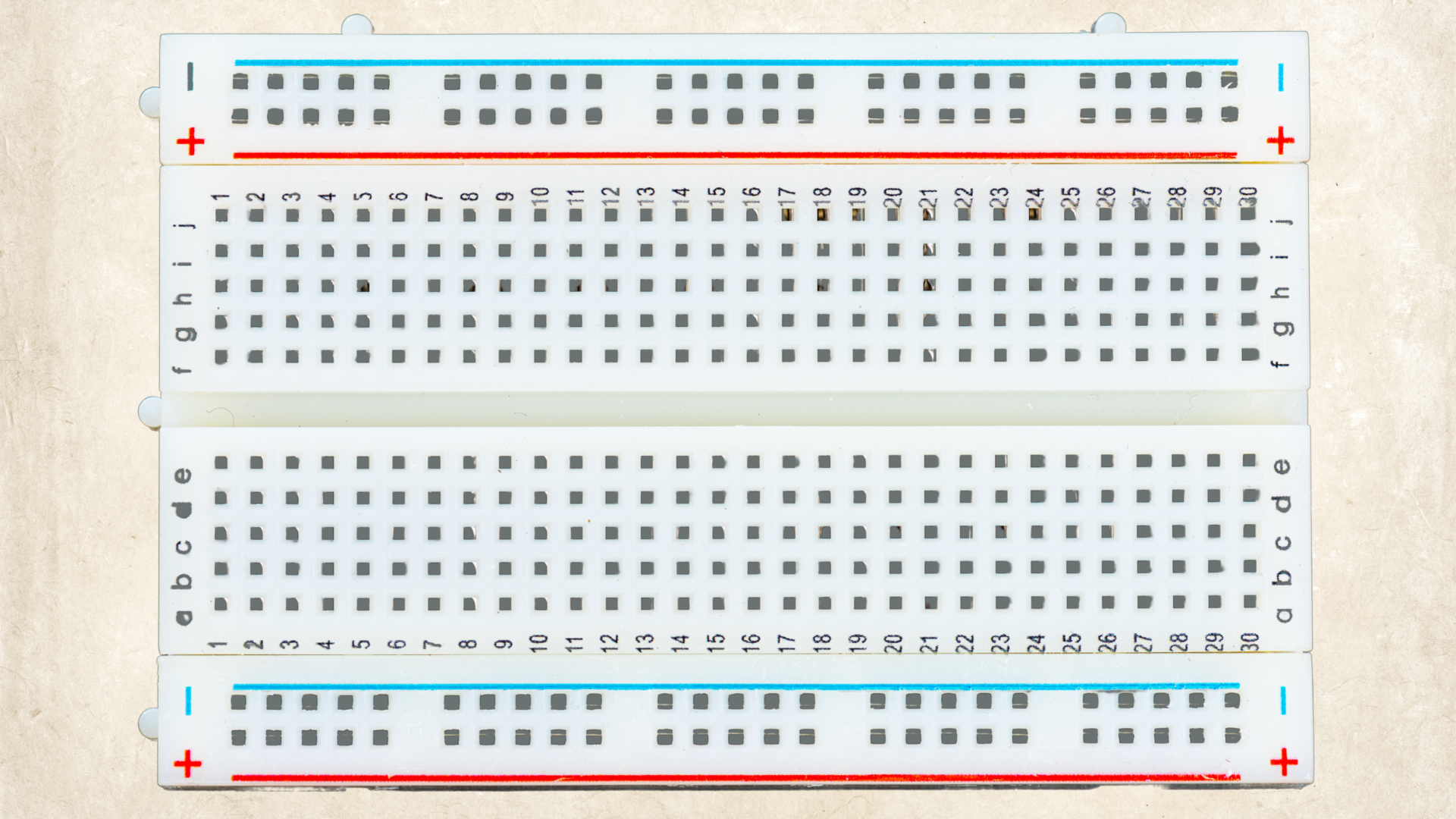
A breadboard is your best friend for prototyping. It lets you test circuits safely, make mistakes, pull wires right back out, and try again in seconds, all without needing any special tools.
In this tutorial, you will learn:
What a breadboard actually is and why it has that weird name.
How the secret hidden connections work underneath the plastic.
How the rows and columns are marked so you never plug a wire into the wrong spot.

Here’s a list of all the parts you need to build the DIY Rotating LED Clock Display. Each part links to Amazon. If a link doesn’t work, don’t worry - we’ve also added tips on how to find a replacement.


Here’s a list of all the tools you’ll need to build the DIY Rotating LED Clock Display. Each tool links to Amazon. If a link isn’t available, we’ve included tips on how to find another one.

Here’s a list of all the parts you need to build the DIY Rotating LED Clock Display. Each part links to Amazon. If a link doesn’t work, don’t worry - we’ve also added tips on how to find a replacement.
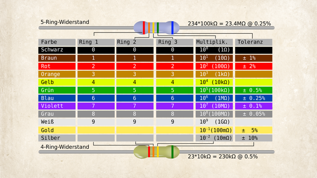
Resistors are essential electronic components that limit the flow of electric current in a circuit. Because they’re so small, their resistance value (measured in ohms, Ω) is usually marked with colored bands instead of numbers. Here's how to read them:
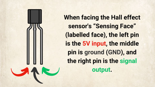
What Is a Hall Effect Sensor?
A Hall Effect Sensor is a small electronic component that detects magnets. When a magnet comes close, it sends a signal to other devices, like an Arduino or an LED light. Think of it as a tiny switch that turns on whenever a magnet is nearby.