
How to use LEGO Mindstorms Clutch
A clutch is a mechanical device that is used for engaging or disengaging power transmission. Now we will see how we can make such a device using LEGO.
- #908
- 30 Jul 2018
Every teacher/instructor can conduct classes with students using these resources. You need to motivate and organize the students. We provide the technical theory, tasks, instructions, programs and everything needed.


A clutch is a mechanical device that is used for engaging or disengaging power transmission. Now we will see how we can make such a device using LEGO.


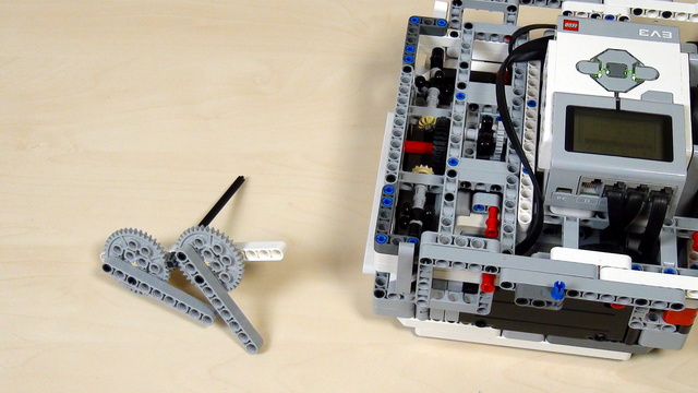
Time to lift the robot. The first approach is by using the 40 teeth gear wheels that come with the LEGO Mindstorms EV3 and NXT robotics sets.

Build a similar mechanism to this one. Similar, but for your robot. This is the task for you. Try, give yourself half and hour or even an hour.

Connect the attachment to the box robot and find the correct number of rotations of the middle motor that would bring the robot up and forward and would attach it to the mission model.


How great is the great attachment for lifting that we built in this course? How many times can it lift the robot without making an error? How great are your attachments and how could you test them? - the answer is simple. Just try 10 times and they should work at least 9 of them as our attachment is.


Here is our solution for preventing torsion and bending of the LEGO Mindstorms EV3 axles.


How to align the wheels and how much should you push for this solution?


There were a few problems with the 40 teeth gears that we were using. Let's list some of them


In this tutorial, we add another mission to our current program. This mission is - hanging the Gecko from the FIRST LEGO League Animal Allies.


We calculate the number of rotatios when a gear system is involved. The driving wheel will have to do a number of rotations for the driven wheel to rotate to a desired number of degrees. In our specific case when the driven gear wheel is rotate to about 90 degrees the legs will lift the robot.


This is a teacher's note about the math behind calculating gear ratios with for our lifting attachment. It math model we build in previous tutorials is not exactly correct and here is the explanation why.


Sometimes the answer that you get by calculating seems not to be right. Is it the calculation that is wrong. Probably it is not the calculation, but something is happening with the robot.


The task in this tutorial is to execute the program 10 times and to do it yourself. If you have your attachment then use it. If you have our attachment then use it. But execute the program 10 times and make sure that it works.


If you've done the calculation following the previous tutorials you would arrive at a result of 18.75 rotations. But this is not the correct answer. The calculation is wrong, because the math model that we've built, although kind of obvious, is not correct. When experimenting the correct number of rotations would be 37.5. This is a large difference. Two times larger. Exactly two times large. Something should be happening here - and this thing is "planetary mechanism"

Calculate the number of rotations you have to do with the motor to rotate the final small 8 teeth driving gear wheel to 1.25 rotations?


What should you as a teacher know when the students are trying to achieve a program and robot attachment that could reproduce their behaviour 9 out of 10 times.


What should you do as a teacher when the students are calculating the gear ratios and number of needed rotations?


In the previous video, we found the correct answer for our task and it is 18.75, or is it?